Mathematical Modelling , Simulation and Validation of Two wheeled self balancing robot
An Analytical and Experimental Approaches
Project Information
- Keywords: Mathematical Modelling ,System identification, Control system design, Robot fabrication & Validation
- Supervisor & Mentor: Asst Prof. Deependra Neupane
- Team:
- Ranish Devkota, Gokarna Baskota, Sadanand Paneru
Facility used: Robotics club
Project Overview
The main Idea of this project revolves around the classical problem of Balancing inverted pendulum with active controller design. This project focuses on Mathematical Modelling of the components used , Design of PID Controller with identified system in Matlab and Implementing the designed controller in modelled robot to give comparative analogy and proof of system identification as well as stable control design.
Methodology
Mathematical modelling of the major components of the system had been done both via classical techniques of as well as modern Data driven approaches.
.jpg)
back-emf.jpeg)

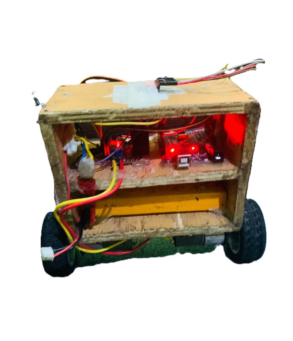
Results

The robot was Balanced and from the result it is clear that the modelling had been quite successful as both ar in close cohision. The tunung as well as randomness in the environmental conditions make the controller design challanging , however irrespective of the forces, robot stand still signifying the system design successful.
Conclusion
The analytical and experimental approaches gives both quality of the real world system limitations as well as ability for control and make inheriently unstable system stable. The significance of system identification as well as mathematical design is demonstrated as the effective inclision of simulations could have been done. however there are certain limitations such as: